8-1
利用f4bar程式
function [data,form] = f4bar(r,theta1,theta2,td2,tdd2,mode,linkdrive)
%
%function [data,form] = f4bar(r,theta1,theta2,td2,tdd2,mode,linkdrive)
% This function analyzes a four-bar linkage when the crank is the
% driving link. The input data are:
% theta1,theta2 are angles in degrees
% r=[r1 r2 r3 r4]= lengths of links(1=frame)
%td2 = crank or coupler angular velocity (rad/sec)
%tdd2 = crank or coupler angular acceleration (rad/sec^2)
%mode = +1 or -1. Identifies assembly mode
%linkdrive = 0 for crank as driver; 1 for coupler as driver
%data (1:4,1) = link positions for 4 links
%data (1:4,2) = link angles in degrees
%data (1:4,3) = link angular velocities
%data (1:4,4) = link angular accelerations
%data (1,5) = velocity of point Q
%data (2,5) = velocity of point P
%data (3,5) = acceleration of point Q
%data (4,5) = acceleration of point P
%data (1,6) = position of Q
%data (2,6) = position of P
%form = assembly status. form = 0, mechanism fails to
% assemble.
% program revised from Waldron's Textbook
% Revised:DSFON, BIME, NTU. Date: Feb. 7, 2007
if nargin<7,linkdrive=0;end
if nargin<6,mode=1;end
data=zeros(4,6);
% if coupler is the driver, interchange the vetor 3 & 2
if linkdrive==1,r=[r(1) r(3) r(2) r(4)];end
rr=r.*r;d2g=pi/180;
[theta,td,tdd]=deal(zeros(4,1));
theta(1:2)=[theta1 theta2]*d2g;
t1=theta(1);tx=theta(2);
s1=sin(t1);c1=cos(t1);
sx=sin(tx);cx=cos(tx);
% position calculations
A=2*r(1)*r(4)*c1-2*r(2)*r(4)*cx;
C=rr(1)+rr(2)+rr(4)-rr(3)-2*r(1)*r(2)*(c1*cx+s1*sx);
B=2*r(1)*r(4)*s1-2*r(2)*r(4)*sx;
pos=B*B-C*C+A*A;
if pos>=0,
form=1;
% Check for the denominator equal to zero
if abs(C-A)>=1e-5
t4=2*atan((-B+mode*sqrt(pos))/(C-A));
s4=sin(t4);c4=cos(t4);
t3=atan2((r(1)*s1+r(4)*s4-r(2)*sx),(r(1)*c1+r(4)*c4-r(2)*cx));
s3=sin(t3);c3=cos(t3);
else
% If the denominator is zero, compute theta(3) first
A=-2*r(1)*r(3)*c1+2*r(2)*r(3)*cx;
B=-2*r(1)*r(3)*s1+2*r(2)*r(3)*sx;
C=rr(1)+rr(2)+rr(3)-rr(4)-2*r(1)*r(2)*(c1*cx+s1*sx);
pos=B*B-C*C+A*A;
if pos>=0,
t3=2*atan((-B-mode*sqrt(pos))/(C-A));
s3=sin(t3); c3=cos(t3);
t4=atan2((-r(1)*s1+r(3)*s3+r(2)*sx),...
(-r(1)*c1+r(3)*c3+r(2)*cx));
s4=sin(t4);c4=cos(t4);
end
end
theta(3)=t3;theta(4)=t4;
%velocity calculation
td(2)=td2;
AM=[-r(3)*s3, r(4)*s4; -r(3)*c3, r(4)*c4];
BM=[r(2)*td(2)*sx;r(2)*td(2)*cx];
CM=AM\BM;
td(3)=CM(1);td(4)=CM(2);
%acceleration calculation
tdd(2)=tdd2;
BM=[r(2)*tdd(2)*sx+r(2)*td(2)*td(2)*cx+r(3)*td(3)*td(3)*c3-...
r(4)*td(4)*td(4)*c4;r(2)*tdd(2)*cx-r(2)*td(2)*td(2)*sx-...
r(3)*td(3)*td(3)*s3+r(4)*td(4)*td(4)*s4];
CM=AM\BM;
tdd(3)=CM(1);tdd(4)=CM(2);
%store results in array data
% coordinates of P and Q
if linkdrive==1,
c2=c3;c3=cx;s2=s3;s3=sx;
r(2:3)=[r(3) r(2)];theta(2:3)=[theta(3) theta(2)];
td(2:3)=[td(3) td(2)];tdd(2:3)=[tdd(3) tdd(2)];
else
c2=cx;s2=sx;
end
for j=1:4,
data(j,1:4)=[r(j)*exp(i*theta(j)) theta(j)/d2g td(j) tdd(j)] ;
end % position vectors
data(1,5)=r(2)*td(2)*exp(i*theta(2));%velocity for point Q
data(2,5)=r(4)*td(4)*exp(i*theta(4));%velocity for point P
data(3,5)=r(2)*(i*tdd(2)-td(2)*td(2))*exp(i*theta(2));%acc of Q
data(4,5)=r(4)*(i*tdd(4)-td(4)*td(4))*exp(i*theta(4));%acc of P
data(1,6)=data(2,1);%position of Q, again
data(2,6)=data(1,1)+data(4,1);% position of P
%find the accelerations
else
form=0;
if linkdrive==1,
r=[r(1) r(3) r(2) r(4)];
for j=1:4, data(j,1)=r(j).*exp(i*theta(j));end % positions
end
end
輸入[val,form]=f4bar([4 3 3 5],0,45,10,0,-1,0)
位置 角速度 角加速度
I (0.0,0.0) 0 0
II (2.1,2.1) 10.0000 0
III (3.2,4.9) 16.2681 491.4428
IV (4.0,0.0) 4.9677 383.6120
8-2
利用drawlinks程式為之
此程式有利用到f4bar的值
所以在程式中只要設定好桿長以及角度
再加上模式與驅動桿的設定,就可以完成
function [values]=drawlinks(r,th1,th2,mode,linkdrive)
if nargin<5,linkdrive=0;end
if nargin<4,mode=1;end
[values b]=f4bar(r,th1,th2,0,0,mode,linkdrive);
rr=values(:,1);
rr(3,1)=rr(1,1)+rr(4,1);
rx=real(rr(:,1));rx(4)=0;
ry=imag(rr(:,1));ry(4)=0;
if b==1
plot([0 rx(1)],[0 ry(1)],'k-','LineWidth',4);
hold on;
if linkdrive==0
plot([0 rx(2)],[0 ry(2)],'b-','LineWidth',1.5);
plot([rx(2) rx(3)],[ry(2) ry(3)],'r-','LineWidth',2);
else
plot([0 rx(2)],[0 ry(2)],'r-','LineWidth',2);
plot([rx(2) rx(3)],[ry(2) ry(3)],'b-','LineWidth',1.5);
end
plot([rx(1) rx(3)],[ry(1) ry(3)],'g-','LineWidth',1.5);
plot(rx,ry,'bo');
text(0,0,' O');text(rx(1),ry(1),' R');
text(rx(2),ry(2),' P');text(rx(3),ry(3),' Q');
else
fprintf('Combination of links fail at degrees %6.1f\n',th2);
end
axis equal
grid on

8-3
利用drawlimits程式
function drawlimits(r,th1,sigma,driver)
[Qstart, Qstop]=fb_angle_limits(r,th1,driver)
clf;
[values b]=f4bar(r,th1,Qstart,0,0,sigma,driver);
rr=values(:,1);
rr(3)=rr(1)+rr(4);
rx=real(rr);rx(4)=0;
ry=imag(rr);ry(4)=0;
if b==1
plot([0 rx(1)],[0 ry(1)],'k-','LineWidth',4);
hold on;
if driver==0
plot([0 rx(2)],[0 ry(2)],'b-','LineWidth',1.5);
plot([rx(2) rx(3)],[ry(2) ry(3)],'r-','LineWidth',2);
else
plot([0 rx(2)],[0 ry(2)],'r-','LineWidth',2);
plot([rx(2) rx(3)],[ry(2) ry(3)],'b-','LineWidth',1.5);
end
plot([rx(1) rx(3)],[ry(1) ry(3)],'-g');
plot(rx,ry,'bo');
text(0,0,' O');text(rx(1),ry(1),' R');
text(rx(2),ry(2),' P');text(rx(3),ry(3),' Q');
text(rx(2)/2,ry(2)/2,['s1=' num2str(Qstart,'%6.1f')]);
else
fprintf('Combination of links fails at degrees %6.1f\n',Qstart);
end
[values b]=f4bar(r,th1,Qstop,0,0,sigma,driver);
rr=values(:,1);
rr(3)=rr(1)+rr(4);
rx=real(rr);rx(4)=0;
ry=imag(rr);ry(4)=0;
if b==1
if driver==0
plot([0 rx(2)],[0 ry(2)],'b-','LineWidth',1);
plot([rx(2) rx(3)],[ry(2) ry(3)],'r-','LineWidth',1.5);
else
plot([0 rx(2)],[0 ry(2)],'r-','LineWidth',1.5);
plot([rx(2) rx(3)],[ry(2) ry(3)],'b-','LineWidth',1);
end
plot([rx(1) rx(3)],[ry(1) ry(3)],'g-');
plot(rx,ry,'bo');
text(rx(2),ry(2),' p');text(rx(3),ry(3),' q');
text(rx(2)/2,ry(2)/2,[' s2=' num2str(Qstop,'%6.1f')]);
else
fprintf('Combination of links fail at degrees %6.1f\n',Qstop);
end
axis equal
grid on
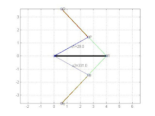
輸入drawlimits([4 3 3 5],0,1,0)
Qstart = 28.9550
Qstop = 331.0450
如圖所示

8-4
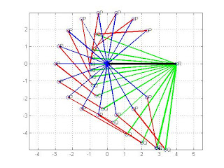
for i=0:20:360
drawlinks([4 3 3 5],0,i,-1,0);
pause(1)
end
Combination of links fail at degrees 0.0
Combination of links fail at degrees 20.0
Combination of links fail at degrees 340.0
Combination of links fail at degrees 360.0
我們會發現在某些角度譬如說20,340,360等沒有值
因為在旋轉四連桿的過程中,必須符合葛拉索定理
其實也就是連桿之間要構成封閉三角形的樣子
如果沒有構成封閉三角刑,那麼四連桿當然無法運作
r1 + r2 < r3 +r4
|r1 -r2|>|r3 - r4|
如下圖

8-5
利用網頁上講義的程式move_4paths
此程式必須用到相當多其他的子程式
例如f4bar.m funcion, f4limits.m, fb_angle_limits.m
等等,可以說是一個整合的結果
function move_4paths(r,r6,th6,nlink,th1,td2,tdd2,sigma,driver,ntimes,npts)
%
%function move_4paths(r,r6,th6,nlink,th1,td2,tdd2,sigma,driver,ntimes,npts)
%
%draw the positions of four-bar links
%call f4bar.m funcion, f4limits.m, fb_angle_limits.m, body.m
%
%Inputs:
% r: row vector for four links
% th1: frame angle
% th2: crank angle or couple angle
% td2,tdd2:angular velocity and acceleration of the driving link.
% sigma: assembly mode
% driver: 0 for crank, 1 for coupler
% ntimes: no. of cycles
% npts: number of points divided
% r6,rh6,nlink:additional length and angle for nlink link.
%example:
% move_4paths([4 2 3 4],2,-30,3,0,10,0,1,0,4,100)
%
%clf;
if nargin<10, ntimes=3;npts=100;end;
figure(1);
[Qstart, Qstop]=fb_angle_limits(r,th1,driver);
npoint=abs(npts);
th2=linspace(Qstart,Qstop,npoint);
val=zeros(6,npoint);
for i=1:npoint,
[vr b]=f4bar(r,th1,th2(i),td2,tdd2,sigma,driver);
[para]=body(r6,th6,vr,nlink);
val(1:3,i)=[vr(1,1);vr(2,1);vr(1,1)+vr(4,1)];
val(4:6,i)=[para(1);para(3);para(2)];
end
x=real(val);y=imag(val);
h=f4limits(r,th1,sigma,driver);
line(x(5,:)',y(5,:)','color','r','linestyle',':');
line(x(4,:)',y(4,:)','color','b','linestyle','-.');
line(x(6,:)',y(6,:)','color','k','linestyle',':');
range=1.2*([min(min(x)) max(max(x)) min(min(y)) max(max(y))]);
axis(range);axis equal;grid off;
for i=2:4,set(h(i),'erasemode','xor');end
h0=patch('xdata',[],'ydata',[],'erasemode','xor','facecolor','r',...
'marker','o');
i=0;s=-1;axis off;
for m=1:ntimes
s=-s;
if abs(Qstop-Qstart-360)<1,i=0;s=1;end;
while 1,
i=i+s;
if i>npoint|i==0,break;end;
set(h(2),'xdata',[0 x(2,i)], 'ydata',[0 y(2,i)]);%crank
set(h(3),'xdata',[x(2,i) x(3,i)], 'ydata',[y(2,i) y(3,i)]);%coupler
set(h(4),'xdata',[x(1,i) x(3,i)], 'ydata',[y(1,i) y(3,i)]);%Rocker
set(h0,'xdata',[x(4:6,i)], 'ydata',[y(4:6,i)]);
drawnow; %flush the draw buffer
pause(0.1);
end
end % for m loop
function h=f4limits(r,th1,sigma,driver)
[Qstart, Qstop]=fb_angle_limits(r,th1,driver)
[values b]=f4bar(r,th1,Qstart,0,0,sigma,driver);
if b==1,
h=draw4link(values,driver);
else
fprintf('Combination of links fails at degrees %6.1f\n',Qstart);
end
[values b]=f4bar(r,th1,Qstop,0,0,sigma,driver);
if b==1,
h=draw4link(values,driver);
else
fprintf('Combination of links fails at degrees %6.1f\n',Qstart);
end
axis equal
grid on
輸入
move_4paths([4 3 3 5],0,45,3,0,0,0,1,0,4,100)
可得下面的影片
2 則留言:
第二項題目沒有執行程式,也沒有速度圖
你可以用小畫家畫標上速度就可啦
張貼留言